| I/O |
|---|
 Patch audio input |
 Patch audio output |
 MIDI Note input module |
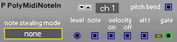 MIDI Note input module |
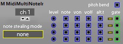 MIDI 4 Note input module |
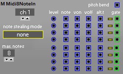 MIDI 8 Note input module |
 MIDI CC input module |
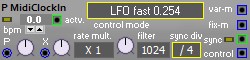 MIDI clock in |
 MIDI Note output module |
 MIDI CC output module |
 MIDI Program Change output module |
 MIDI RPN and NRPN output module |
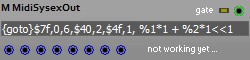 Midi SysEx output |
 Sync Wren instances |
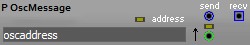 Send or receive OSC |
 Controls the patch mutator |
 Controls the patch mutator |
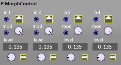 Controls morphing |
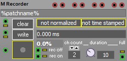 Wave recorder |
| OSC1 |
|---|
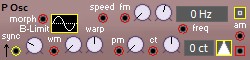 Audio rate sine tri saw square oscillator |
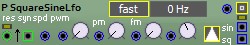
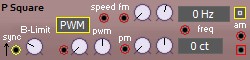 Audio rate square oscillator with PWM |
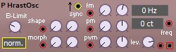 DPW Saw by HrastProgrammer |
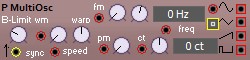 Mult waveform oscillator |
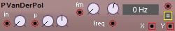
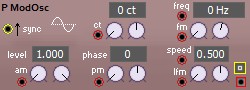 Audio rate sine oscillator with extra modulation |
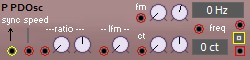 Audio rate phase distorted sine oscillator |
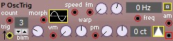
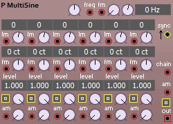
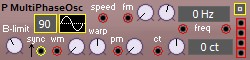 Audio rate sine tri saw square multi phase oscillator |
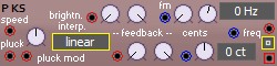 A Karplus-Strong oscillator |
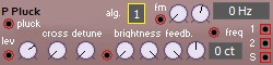 A Karplus-Strong oscillator |
 Audio rate sine tri saw square burst |
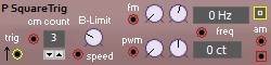 Audio rate square burst with PWM |
 Audio rate noise generator |
 Audio rate clocked noise |
 Audio rate Perlin noise generator |
 Audio rate clocked Perlin noise generator |
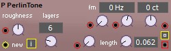 Audio rate Perlin noise generator |
 Audio rate strange attractor module |
 Audio rate strange attractor module |
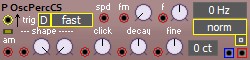 Percussion oscillator |
| OSC2 |
|---|
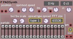 FFT based additive oscillator |
 Audio graph |
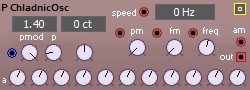 Chladnic oscillator |
 Wave player |
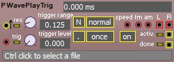 Triggerd Wave player |
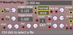 Triggered Wave player |
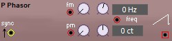
 NM Classic like master OSC, no audio |
 audio rate positive only saw |
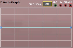 Audio graph |
 DTMF generator |
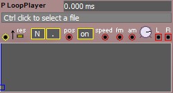 Wave player |
| LFO |
|---|
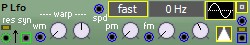 Control rate multi waveform oscillator |
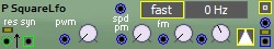 Control rate square oscillator |
 Control rate square and sine oscillator |
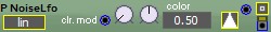 Control rate noise generator |
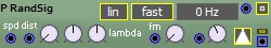 Interpolated random generator |
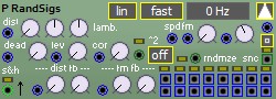 Multiple interpolated random generators |
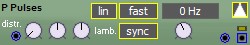 Random pulses generator |
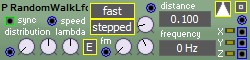 Control rate 3D random walk generator |
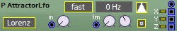 Control rate strange attractor module |
 Control rate strange attractor module |
 Curent time |
 Control rate multi waveform burst |
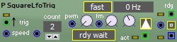 control rate square burst |
 control rate clocked noise |
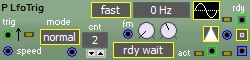
 clock generator |
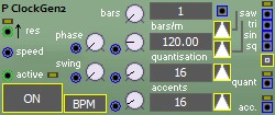 DataGraph clock generator |
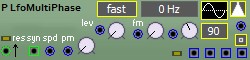 Control rate multi phase multi waveform oscillator |
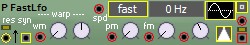 Audio rate multi waveform LFO |
| Env |
|---|
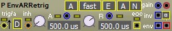 Retriggerable AR envelope |
 Retriggerable AR envelope |
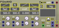 Attack Hold Decay envelope |
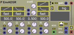 Attack Decay Sustain Release envelope |
 freq |
 Envellope controller |
 Envelope follower |
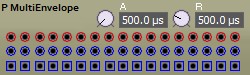 Multi envelope follower |
 A detector module, phase, frequency, amplitude |
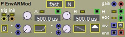
 non retriggerable AR envelope |
 12 dB resonant envelope generator |
| Filter1 |
|---|
 DC cuttoff filter |
 Dual DC cuttoff filter |
 Click removal module |
 averager / lag / portamento filter |
 moving average filter |
 6 dB low and high pass filter |
 6 dB band pass filter |
 6 dB stereo band pass filter |
 6 dB stereo band pass filter |
 12 dB state variable filter |
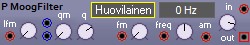 24 dB moog like low pass filter |
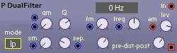 Dual 12 dB filter |
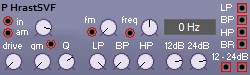 State Variable Filter by HrastProgrammer |
 Integrator / Differentiator |
 Differentiator |
 A 3dB / octave pink filter |
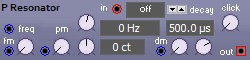 Resonator |
 Tilt filter |
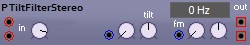 Stereo tilt filter |
 All pass filter |
| Filter2 |
|---|
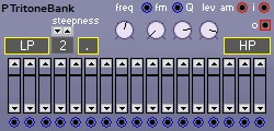 Tritone filter bank |
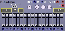 Third filter bank |
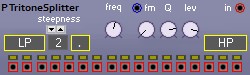 Tritone splitter |
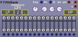 Third filter bank |
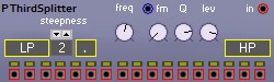 Third splitter |
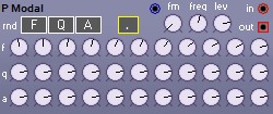 Modal filter |
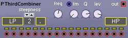 Third combiner |
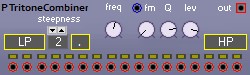 Tritone combiner |
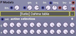 Modal filter type 2 |
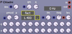 Chladni modal filter |
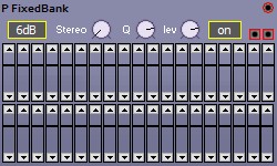 Fixed filter bank |
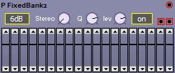 Fixed filter bank |
| Mix |
|---|
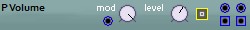 volume controller |
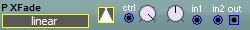 cross fader |
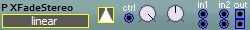 cross fader |
 panner |
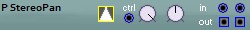 panner |
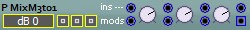 3 to 1 chainable mono mixer |
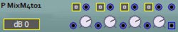 4 to 1 chainable mono mixer |
 2 to 1 chainable stereo mixer |
 5 to 1 chainable stereo mixer |
 1 to 1 chainable three channel mixer |
 1 to 1 chainable four channel mixer |
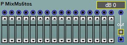 16 channel mixer |
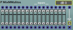 16 channel modulatable mixer |
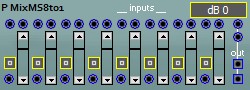 8 ch modulatable stereo mixer |
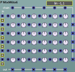 6 to 6 fully chainable mono matrix mixer |
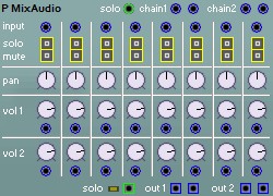 Audio mixer with FX send |
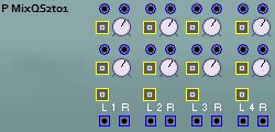 Quad stereo 2 to 1 mixer |
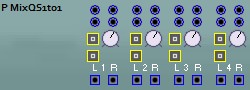 Quad chainable stereo 1 to 1 mixer |
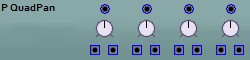 Quad panner |
| Switch |
|---|
 Sample and hold |
 Track and hold |
 2 to 2 switch |
 Multi Sample and hold |
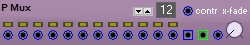 Crossfading multiplexer |
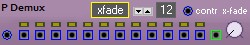 Crossfading de-multiplexer |
 digitally controlled multiplexer |
 digitally controlled de-multiplexer |
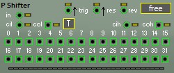
 Serial in to parallel out shifter |
 Value synchronizer |
 Copy and shuffle |
| Ctrl1 |
|---|
 Level scaler |
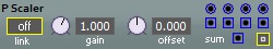
 Proportional scaler |
 RangeConverter module [inrange] -> [low,high] |
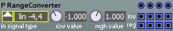 RangeConverter module [inrange] -> [low,high] |
 Modulatiion depth controller |
 LevelConverter module [inrange] -> [outrange] |
 dynamic level type switcher |
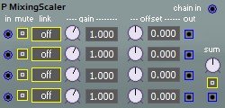 Fourfold mixing level scaler |
 Change detector |
 Scaled clipper |
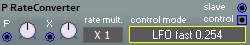 Rate converter |
| Ctrl2 |
|---|
 Rotator |
 Simple rotator |
 Matrix multiplier |
 Rectifier |
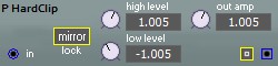 Hard clipping |
 Audio to control rate converter |
 Control rate to audio converter |
 slew rate limiter |
 A Chebyshev polynomial generator, frequency multiplier |
 Square wave rate doubler |
 Saw Mill |
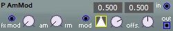 AM RM modulator |
 Wave wrapper, wave shaping |
 Wave wiper, wave shaping |
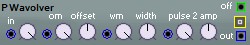 Wavolver |
 Signal shaper |
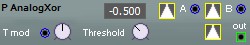 Analog Xor |
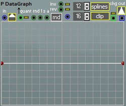 Data graph |
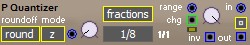
 A number sequence quantizer |
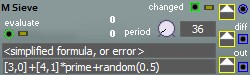 A number sieve |
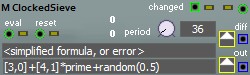 A number sieve |
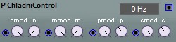 A chladni controller |
 nop |
 global state |
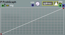 Probability graph |
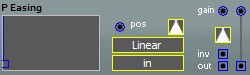 Easing curves |
| Note |
|---|
 Zero crossing frequency detector |
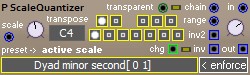
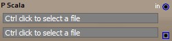 Scala quantizer |
 Equal Division Quantizer |
 Transpose or invert notes |
 Transpose or invert notes |
 Euclidean scale generator |
 Convert note to delay length |
 Level quantizer |
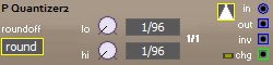 Level quantizer |
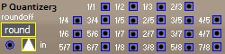 Level quantizer |
 Note quantizer |
 Note quantizer with presets |
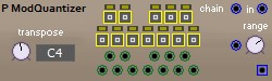 Modulatable Note quantizer |
 Scale randomizer |
 Learning quantizer |
 Convert note into note and octave |
 Combine note and octave |
 Find nearest value in history |
| Math |
|---|
 Inverter |
 Adder / Mixer |
 Pos value Adder |
 Multiplier / VCA / Ringmodulator |
 Pos value Multiplier |
 Exponentiator |
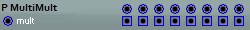 multiplyer array |
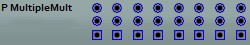 eight multipliers |
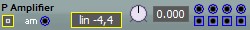 Amplifier |
 Minimum and Maximum of two signals |
 Min, Max or Mix of two signals |
 Analog AND and OR |
 Median of last n samples |
 Reciprocal 1/x |
 Divide x/y |
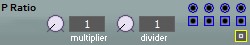 Ratio, multiplier / divider |
 Constant |
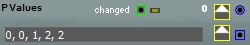
 An arbitrary value module |
 A selectable constant |
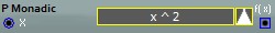 A selectable function of x |
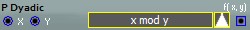 A selectable function of x and y |
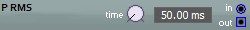 RMS calculator |
 Rectangular to Polar |
 Polar to rectangular |
 out = RangeMap(sig,min,max,0,1) |
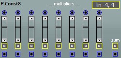 8 constants |
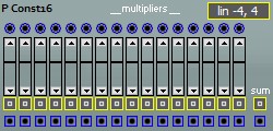 16 constants |
 Exponentiator |
| Logic |
|---|
 logic NOT |
 logic NOT |
 Logic functions |
 Logic functions |
 Logic functions |
 Frequency divider |
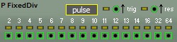 Fixed frequency divider |
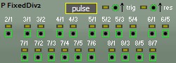 Fixed fractional frequency divider |
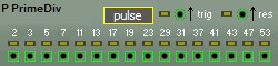 Fixed prime divider |
 Frequency divider |
 D type flip flop |
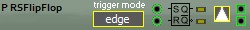 RS type flip flop |
 Pulse Sync |
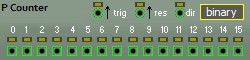 Up down counter |
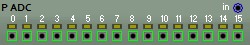 Analog to Digital Converter |
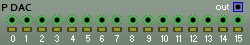 Digital to Analog Converter |
 Phase detector with low pass |
 Compare two inputs for < = > |
 Logic selector |
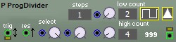 Programmable frequency divider |
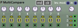 Stacked window comparator |
 Pulse delay |
 Pulse skipper |
 Rungler |
 Logic shift register |
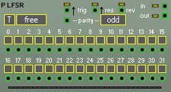 Linear feedback shift register |
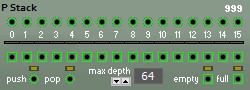 Binary stack |
 Quad Bernoulli gate |
| Seq1 |
|---|
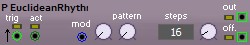 Euclidean Rhythm generator |
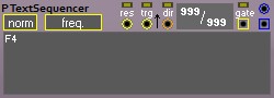
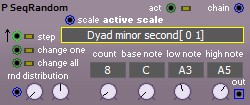 Random note sequencer |
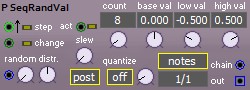 Random value sequencer |
 A Morse code generator |
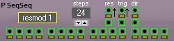 Sequencer sequencer |
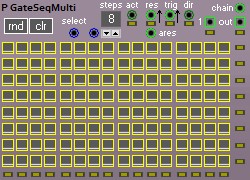
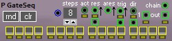 Gate sequencer |
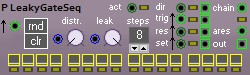 Leaky gate sequencer |
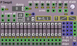 16 steps sequencer |
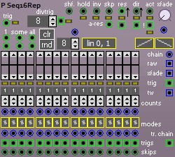 16 steps repeating sequencer |
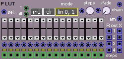 Lookup table |
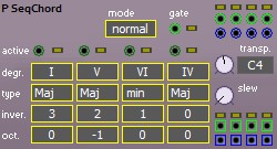 Chord sequencer |
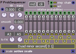 Probabilistic sequencer |
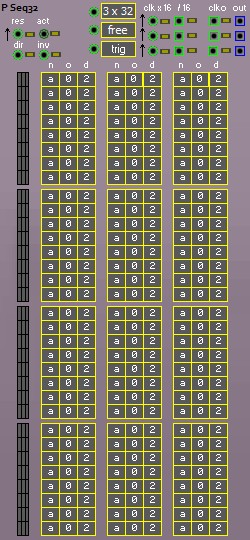 3 x 32 or 1 x 96 note sequencer |
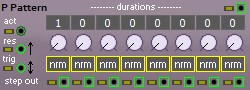 A rhytmic pattern generator |
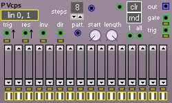 16 steps voltage controlled pattern sequencer |
 Frequency divider |
 Primes Rhythm generator |
| Seq2 |
|---|
 1 - 11 step sequencer |
 arbitrary length sequencer |
 Sequencer step |
 Clocked sequencer step |
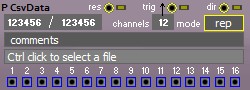 16 channel CSV data player |
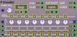 Building block for klee like sequencer |
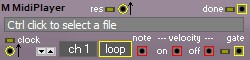 A simple MIDI file player |
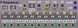
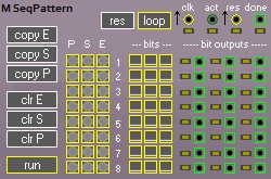 Pattern sequencer |
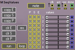 Pattern sequencer |
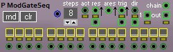 Modulated gate sequencer |
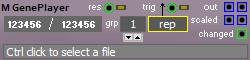 Gen player |
 Gate sequencer |
| Gen1 |
|---|
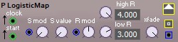 Logistic map module |
 ' Poetry' generator |
 Arpeggiator |
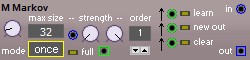 Markov chain |
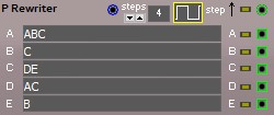 A rule rewriter |
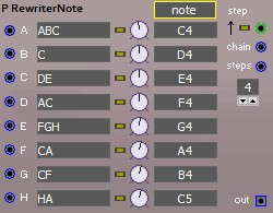 A note based rule rewriter |
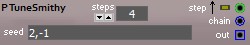 A number sequence generator |
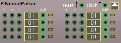 Wiard style neural pulser |
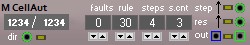 A cellular automaton |
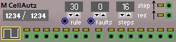 A cellular automaton |
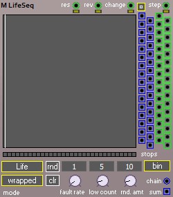 Life sequencer |
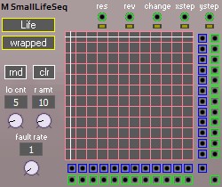 Small life sequencer |
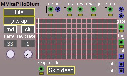 Life sequencer inspired by PHOBoS |
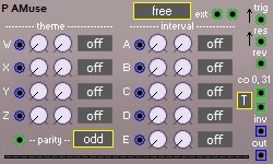 A MUSE like generator |
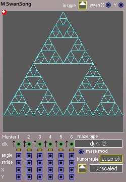 Swan song generator |
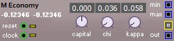 Wealth distribution simulation |
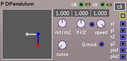 Double pendulum simulation |
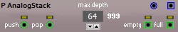 Analog stack |
 Analog queue |
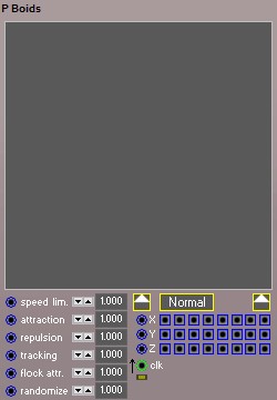 Boids |
| Gen2 |
|---|
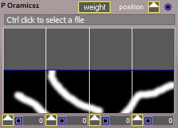 Oramics |
 A file change detector |
| FX |
|---|
 A reverb modeled after freereverb |
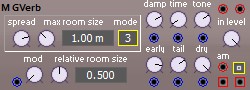 A reverb modeled after gverb |
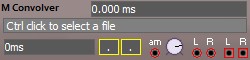 A convolution (reverb) processor |
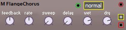 Flanger and Chorus |
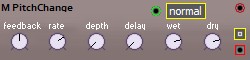 Pitch changer module |
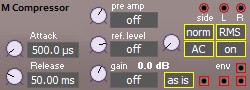 Level Compressor / AGC |
 Noise gate |
 Bode frequency shifter |
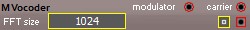 A basic FFT based vocoder |
 A frequency smearing tool |
 Terrain wave generator |
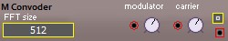 Convoder - experiment |
 Pitch changer module |
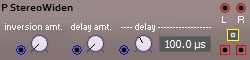 Stereo widener module |
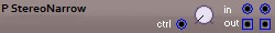 stereo narrower |
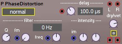 Phase distortion |
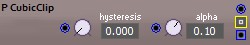 Cubic clipper |
 Cubic clipper, stereo |
 Cubic clipper with fixed settings |
 Cubic clipper with fixed settings |
 A phase splitter |
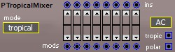 Tropical mixer |
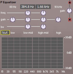 Mono equalizer |
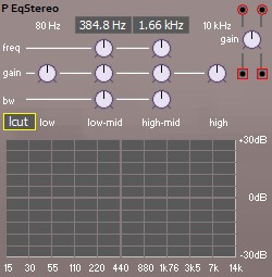 Stereo equalizer |
 Wave folder, wave shaping |
| Delay |
|---|
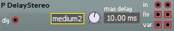
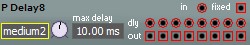
 Variable length delay |
 Variable length poly delay |
 Variable length mixing delay |
 Variable length delay |
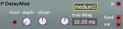 Modulatable delay |
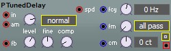 A frequency tuned delay line |
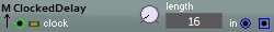 Clocked delay |
 Eight tap variable length delay |
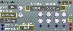
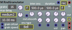 A random granulator |
 A granulator |
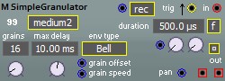 A simple granulator |
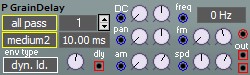 Grained delay |
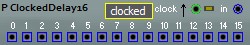 16 out clocked delay |
 All pass filter |
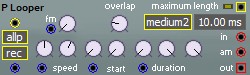 Simple looper |
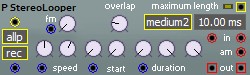 Simple stereo looper |
 Patch audio output |
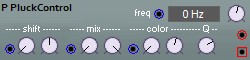 Pluck controller |
| Voice |
|---|
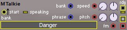 LPC speech module |
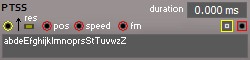 Tiny Speech Synth |
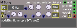 Tiny song synth |
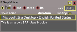 SAPI Speech Synth |
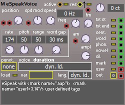 eSpeak Speech Synth |
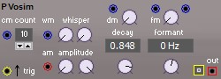 VOSIM |
 A formant / vowel filter |
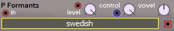 A formant / vowel filter |
| Utility |
|---|
 1 unit blind panel |
 2 unit blind panel |
 3 unit blind panel |
 4 unit blind panel |
 5 unit blind panel |
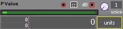 Value indicator |
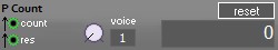 Counter display |
 Frequency counter display |
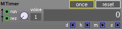 Timer display |
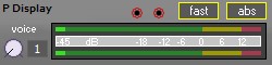 VU meter display |
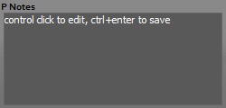 Patch comment |
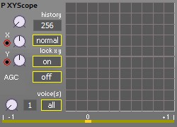 XY oscilloscope |
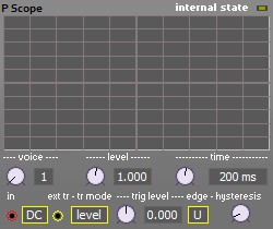 Oscilloscope |
 Oscilloscope |
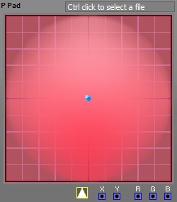 X Y mouse pad control |
 X Y mouse pad control |
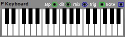 Keyboard |
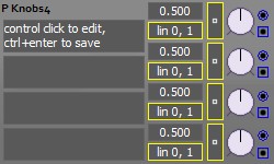 Four knobs |
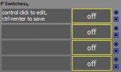 Four switches |
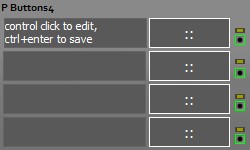 Four momentary switches |
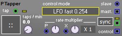 Tap rate detector |
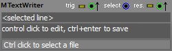 Patch comment written to file |
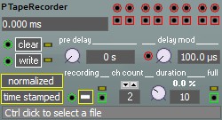
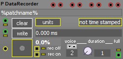 Data recorder |
 mosc's ambiophonic processor |
| Poly |
|---|
 Polyphonic voice splitter |
 Polyphonic voice merger |
 Polyphonic voice summer |
 Polyphonic voice shifter |
 Polyphonic voice selector |
 Polyphonic voice selector |
 Polyphonic voice number |
 Polyphonic voice number |
 Mono Poly switch |
 Multiple mono poly switches |
 Polyphonic voice viewer |